Uprating Midget rear axles
Questions are often asked about how well the Midget rear axle can cope with additional power. The answer is that it depends on which part of the rear axle you are referring to!
Our testing regime
Before I go further, I’ll outline the experience which has led to the comments below.
We have competed intensively in our K series engined Midget, which had 185bhp in normally aspirated form, and has done a decade of serious competing on the orignal rear axle fitted with a limited slip diff and uprated halfshafts.
The type of event which gives the hardest test for the rear axle is use in autotests or autosolos, or motorkhanas and autocrosses as we call them in NZ. When racing, the most stress is placed on the axle as the car leaves the start line thanks to the torque multiplier effect of the gearbox being greatest in first gear. Generally, this happens only once in a race, thereafter the car is in higher gears and the torque experienced by the rear axle is reduced accordingly, and the impact loading of a clutch dump is not present either. In autotests in particular the car is in first gear for usually the whole time, and during the course of a single test will have a great many torque reversals, and several clutch dumps .. one with each handbrake turn!
Hence a day’s autotesting will punish the rear axle more than a whole season’s worth of racing.
In addition, in our case, we have used sticky tyres to transmit the extra power of the K, so this has placed even more load on the axle. So in 10 years competing we have given the rear axle a great deal of punishment.
Differential:
We use a 3.9 standard Midget crown wheel and pinion. It is a replacement 3.9, not an original. This may be significant as the cone angle of the pinion was greater than the original. On the other hand it might not affect it at all! Instinctively I think the sideways thrust between crown wheel and pinion may well be affected by the different angle, but I’ve been too lazy to work it out. All I know is the current CWP has been up to the job.
The reason we fitted the new CW&P is relevant. It’s because the old one broke first time out. However, the reason it broke was not any inherent weakness – it copped a piece of spider pinion which caused one of the pinion teeth to crack.
The real culprit was wheel spin. Without a Limited Slip Diff to lock up both wheels the inside wheel spun much faster than the other, the diff lubrication couldn’t cope and the spiders seized to their shaft. Then one shattered as they were trying to go in opposite directions and something had to give.
At the time, we already had a limited slip diff ready to fit but were waiting for the halfshafts to be made for it. We did rather hope it would survive one event! So we fitted the LSD along with the new CW&P and we’ve had no problems ever since, despite giving the rear axle a real hammering over the period of a decade at the time of writing (said he hastily looking for some wood to touch).
Where this is all leading is that the standard Midget diff will survive the pounding of intense competition if you fit an LSD. It’s a nice change to have a modification which enhances reliability as well as performance!
Halfshafts
Halfshafts, on the other hand, are the weakest link in the Midget’s drive train. This is down to both the material and the spline design, which is an old type which results in concentration of stress at the ends of the splines and at the centre of the halfshaft.
The halfshafts were marginal for the standard engine’s power output, so if contemplating increased power or competition use it is a good idea, and cheaper in the long run, to do something about the halfshafts.
Here are the options:
Modify your existing halfshaft:
The cheapest way of uprating the shaft is to eliminate the stress raiser at the ends of the splines. This is done as follows:
- Waist the halfshaft behind the spline down to the root diameter of the spline so the spline is left standing proud of rather than cut into the halfshaft.
- Machine the shaft to this diameter for 4”
- Then blend out to the original diameter over 6”.
- Blend the ends of the splines inwards as can be seen in the photo (it’s a fine-spline photo but the principle is the same.)
It may seem counter-intuitive that reducing the diameter improves the shaft, but that is the case. The simple reason is that the stress is no longer concentrated in the short distance between diff gear and spline end where the shaft is smallest. Instead, the stress is spread over a much longer length of shaft and so the level of stress is reduced accordingly. There are other more complex issues which concentrate stress which are also addressed by this modification.
Note: It’s a good idea to have the shafts at least crack tested and preferably stress relieved before doing this. The material type (which the heat treatment company will need to know to do the stress relief) is EN17 for later halfshafts, EN8 for early ones.
Use halfshafts made of stronger steel
There are a number of uprated halfshaft options on the market using stronger steel, but surprisingly most repeat the design error. While the better material represents a worthwhile improvement, if the choice is available it’s better to address the design issue as well – usually at little or no extra cost.
There are two separate aspects of the design:
- Eliminate the stress raiser at the ends of the splines as outlined above underModify your existing halfshaft. This may be by buying halfshafts already made like this, or by modifying uprated steel halfshafts made to the original design
- Change the spline pattern to one with fine splines. Not only does, the greater number of splines means that the stress per spline is reduced accordingly, but the V-shape of them spreads the stress over a greater area of halfshaft, around its periphery rather than focusing it to a small circle in the centre as the original rectangular section splines do. In addition, the smaller splines retain a larger root diameter. Each of these features substantially reduce the stress levels in the steel, combined together the effect is dramatic, particularly when the waisting past the end of the spline is done too.
Note that the side gears in the diff will need to be changed to a fine spline pattern as well of course. The LSD’s supplied by Frontline already come with a fine spline option. Alternatively get some made – our ones cost us $NZ70 each to get made.
Our shafts are made from 2767 steel, which is an extremely strong material rated at 100 tons and stronger than EN24, EN30B,EN40B or 4340 which are some of the other steels used. We have them in both the original and fine spline pattern.
All this, limited slip diff and uprated halfshafts, might cost a bit up front but in the long term it’s much cheaper than persevering with standard components which break. And avoids the extra work and DNF disappointments. Not to mention the pleasure factor that driving with an LSD gives 🙂
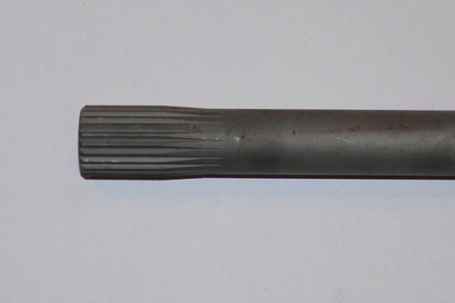
Diff end of halfshaft, showing waisting behind the splines & the blending of the splines to the root diameter. This is a fine spline halfshaft so the waisting is less obvious than for the original splines.
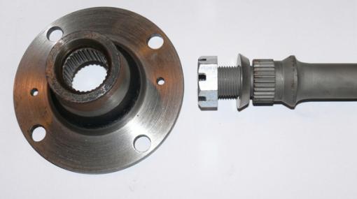
Outer end of uprated halfshaft showing bolt-on flange.
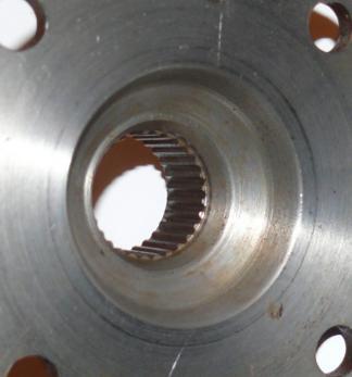
Drive flange inside detail.
